


Description
Fast-Charging Protocol Support:
Supports full mainstream fast-charging protocols.
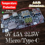
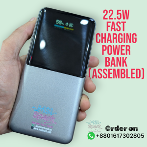
Charging current up to 5A, efficiency up to 96%, output power up to 22.5W (≈95% efficiency).
Automatic load detection and light-load detection.
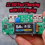
Supports digital tube display and LED indicators.
Built-in protection: overcurrent, short-circuit, charging timeout, overvoltage.
Supported Protocol List:
• PPS / PD3.0 / PD2.0
• QC4+ / QC4 / QC3.0 / QC2.0
• VOOC / DASH / Warp
• Samsung AFC
• Huawei FCP, SCP (5V4.5A / 4.5V1.5A), HSCP
• MediaTek PE2.0 / PE1.1
• SFCP
Battery charging supports:
PD3.0 / PD2.0, AFC, FCP, SCP, PE1.1
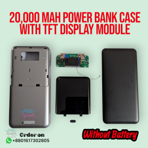
Product Design & Build:
• Compact size with strong performance.
• High-quality materials and optimized PCB design.
• Delivers high efficiency in a small footprint.
• High-power operation may generate heat — normal and safe.
• Board thickness: 6 mm, 8.5 mm with display.
Usage Notes:
Voltage Checking
• After wiring, check with a multimeter to ensure B+ and B- voltages match during charging/discharging.
• Large differences indicate wiring issues or battery aging.
Function Key:
• Single press – Enable Type-C output and show battery level.
• Double press – Close the Type-C output and battery display.
• If external power is present, only the output is turned off.
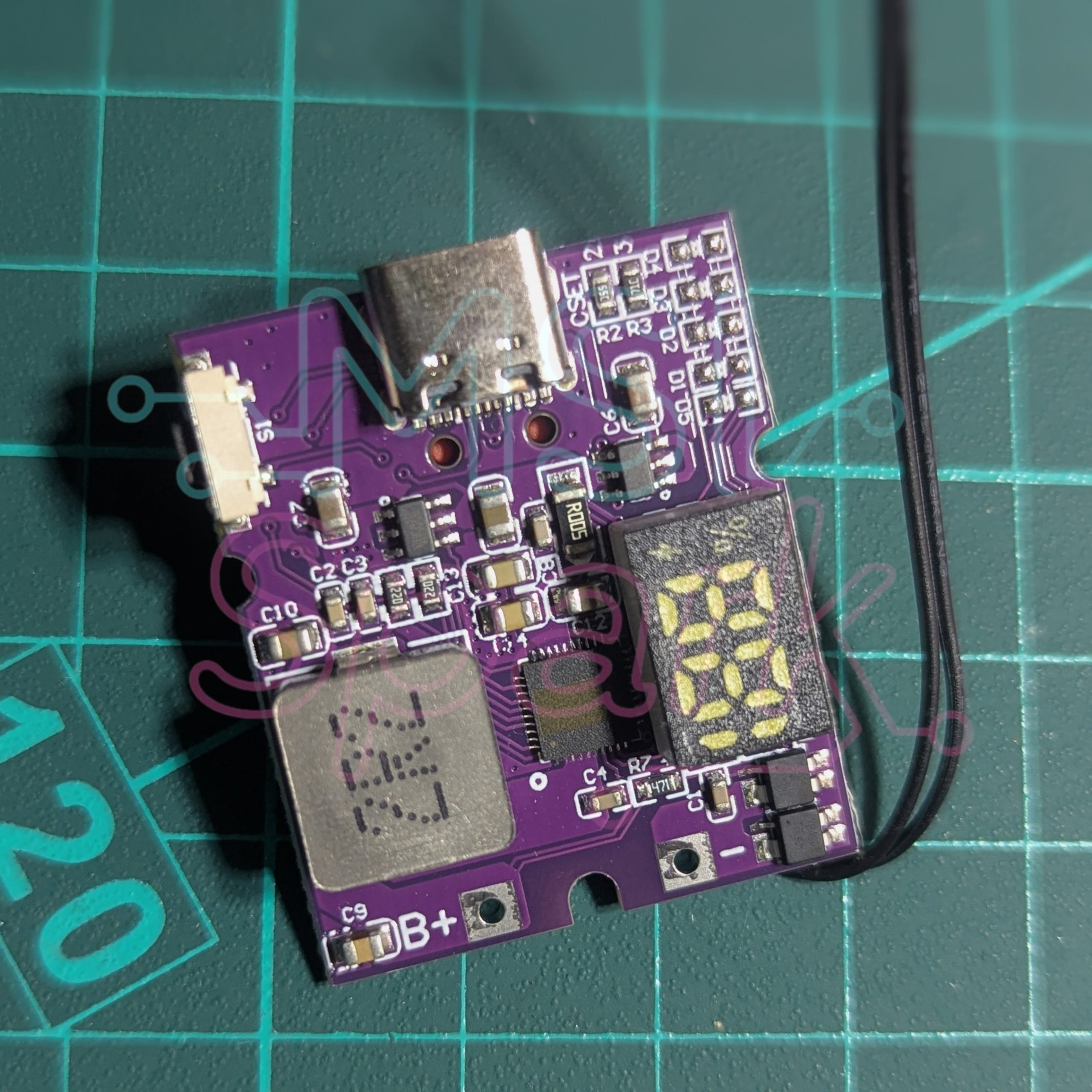
Ports:
Type-C: Supports input & output.
B+: Must be soldered with thick, short wiring.
B-: Same requirement — thick, short, soldered.
Important Precautions Before Use:
• Connect a charger first to verify LED indicators before assembling.
•Do not connect a battery before confirming LED status.
• Battery & Wiring Requirements
• Battery must be soldered, not twisted.
• Wrong polarity will burn the board.
• Wires must be thick and short for proper current delivery.
• Fast-charging version requires 10A, standard version 7A.
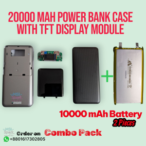
• Batteries must be connected in parallel only, not series.
• Only use a 3.7V lithium battery.
Battery Condition:
Aged batteries can cause incorrect charging or inability to discharge.
If the battery has a protection board, ensure it supports:
>7A (standard)
>10A (fast charge)
Otherwise remove it.
Reverse Connection Warning:
• Reverse polarity always burns the protection ICs and leaves visible marks.
Damage from reverse connection is not covered.
Heat Generation:
• All power modules generate heat — this is normal.
• High-quality ICs ensure safety and long life
Coulomb Meter Notes:
• Battery level may be inaccurate right after wiring.
• Accuracy improves after several full charge/discharge cycles.
Protocol Compatibility Note:
Phone protocols change over time.
Example: older Honor phones supported 5V4.5A SCP, newer ones use 10V2.5A SCP.
→ Always follow the protocol list printed on the board.


eliaseshan96 –
it works wall highly recommend